Partial discharges are a kind of hollow spaces or cracks in the insulation of electrical machines like generators, motors, or transformers. According to IEC 60270 they are local dielectric partial discharges in a part of the insulation system under high voltage stress. This phenomenon is the beginning of a complete breakdown of the insulation system which may lead to enormous damages of the machine or system. We would like to prevent this by detecting the intensity of developing partial discharges at an early stage.
Besides the measurement of partial discharges the tan delta testing is another efficient method to monitor the state of the insulation system of an electrical machine or system. In this case the current flow in the coils is measured in two directions: Firstly, in the intended direction, following the technical stream of the conductor and secondly through the insulation covering the conductor outwards. The better the quality of the insulation the lower the current flow through the enclosing insulation to the earth potential.
The video endoscopy is used for the visual detection of errors or weaknesses inside the machine or system. With this method it is possible to record precise videos or photos of the components or system parts. We use video endoscopy for checks during planned inspections and maintenance works on electrical machines and systems.
Electrical machines and systems warm up during operation and often reach a nominal temperature. But there may be irregularities in the heat distribution. This may happen due to defective or faulty cabling, frictions, or storage problems. Thermographic cameras can localize separate heat zones and weaknesses.
The insulation resistance measurement tests the resistance of the insulation of electrical coils. A direct current, the level of which is determined according to the rated voltage of the machine or system, is used to measure the resistance against the earth potential. The discharge capacity of the insulation system is tested. This measurement is a fix component within the scope of inspections, troubleshooting and commissioning.
The polarisation index measurement, also known as PI measurement, is an insulation measurement extended to ten minutes. The so-called PI factor is then calculated. For this purpose, the insulation values of ten minutes and of one minute will be set in relation to each other. The resulting factor is used to evaluate the cleanliness and dryness of the electrical coil of a generator or motor.
When measuring vibrations, we determine the vibration velocity and the vibration acceleration with a portable vibration meter. No mechanical work on the electrical machine is necessary. Normal operation is not interrupted. This machine diagnostic is ideal for monitoring after inspections or during the commissioning of an electrical machine.
To perform a security check (protection testing) the corresponding system component will be isolated while respecting the five security rules. Then the characteristics of the different system components are recorded. However, the transformers should be tested before a security check (protection testing) (see transformer testing). The settings must be read from the protection relay to adjust the test procedures in the software accordingly. Then the response (pick up) value and the release (drop off) value will be tested and the resetting ratio will be automatically calculated. And finally, the trigger trip time of the circuit breaker will be measured.
The circuit breaker testing can take place as soon as all system parts have been isolated while respecting the five security rules. Then the characteristics of the circuit breaker and the switchgear will be recorded to measure the timing for the on and off processes at the three phases. The proper functioning of the coils will be tested and the insulation resistance will be measured via the main contacts and at the control lines. The resistance of the main contacts can be determined by a micro-ohmmeter.
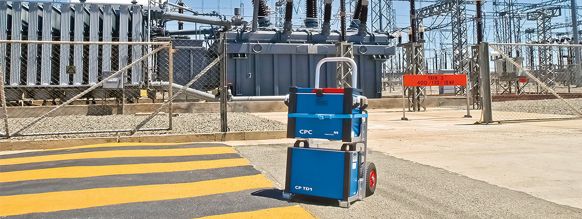
A transformer testing will be performed as soon as the corresponding system parts have been isolated while respecting the five security rules. Subsequently the characteristics of the transformers will be recorded and the transmission ratio of the current and voltage transformers will be tested. At the same time the correct phase position for the current and voltage transformers will be determined. The insulation resistance and the burden will be measured and finally the earthing screws as well as the cable and busbar connections at the transformers will be checked.
On request we will send you all information about our services in this field as well as our comprehensive specifications by email.
